Overview of things needed.
- Toaster oven (keep the inside volume as small as possible)
- Solid state relay (We used the SSR-40DA)
- 18AWG wire or lower
- Wire strippers and cutters
- Soldering Iron
- RTV High-temp Sealant
- High-temp Insulation (this, this and that)
- Controller (We used the Rocket Scream V2)
Preparing the Oven
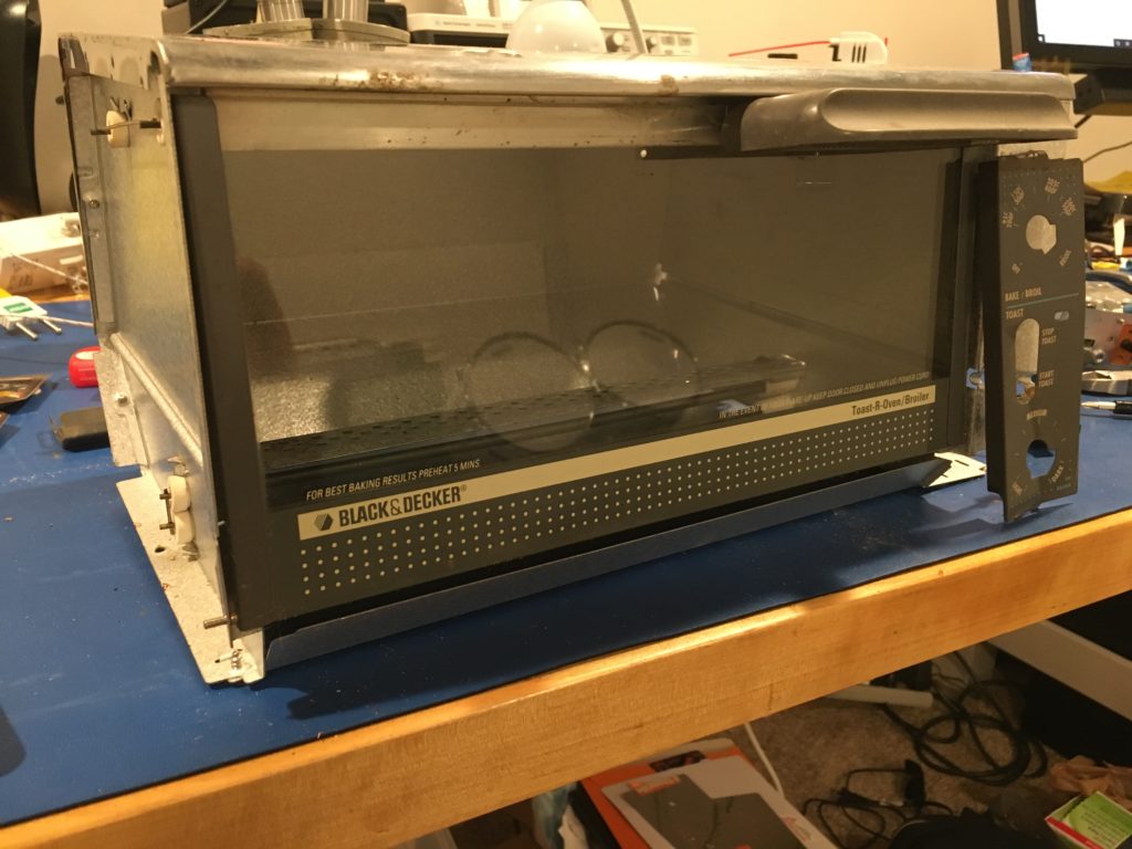
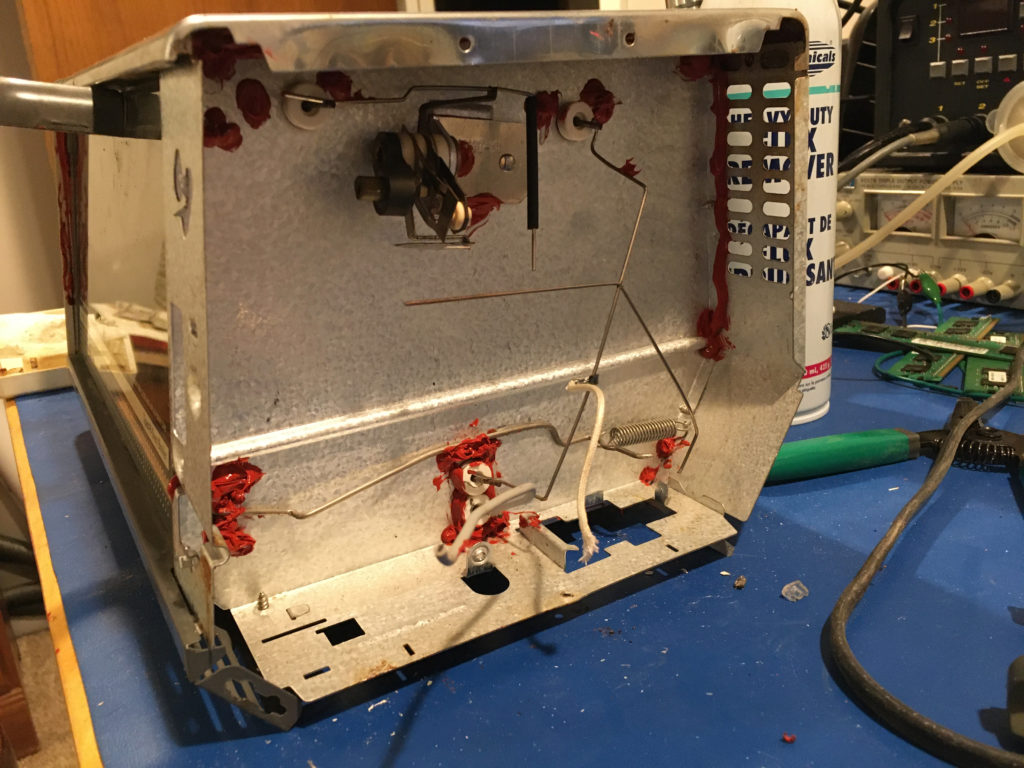
The picture above is our victim toaster oven part-way through gutting it. We roughly followed the instructions given here. We made some slight deviations along the way, which we will try and point out explicitly during this post.
The first step was the gut the machine and give it a quick cleaning. We bought it from a thrift store for $7, so we’re guessing it had seen quite a few pizza slices and burnt pieces of toast. We thought it best to get any food residues out of there before using it for prototyping our electronics designs in-house!
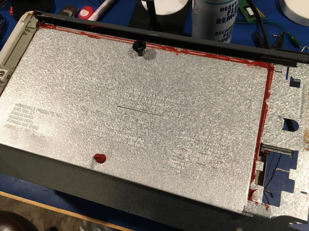
During the cleaning session, we removed a majority of the aforementioned food stuffs. Luckily, nothing was too difficult to remove. We then moved onto trying to make the oven as air-tight as possible. The picture below shows our (messy) attempt. We used RTV sealant. Make sure to get the “high temp” variety that is red. Do try to do this with plenty of ventilation though…it outgasses acetic acid and the smell is enough to make your eyes water a day later.
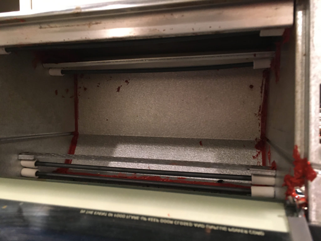
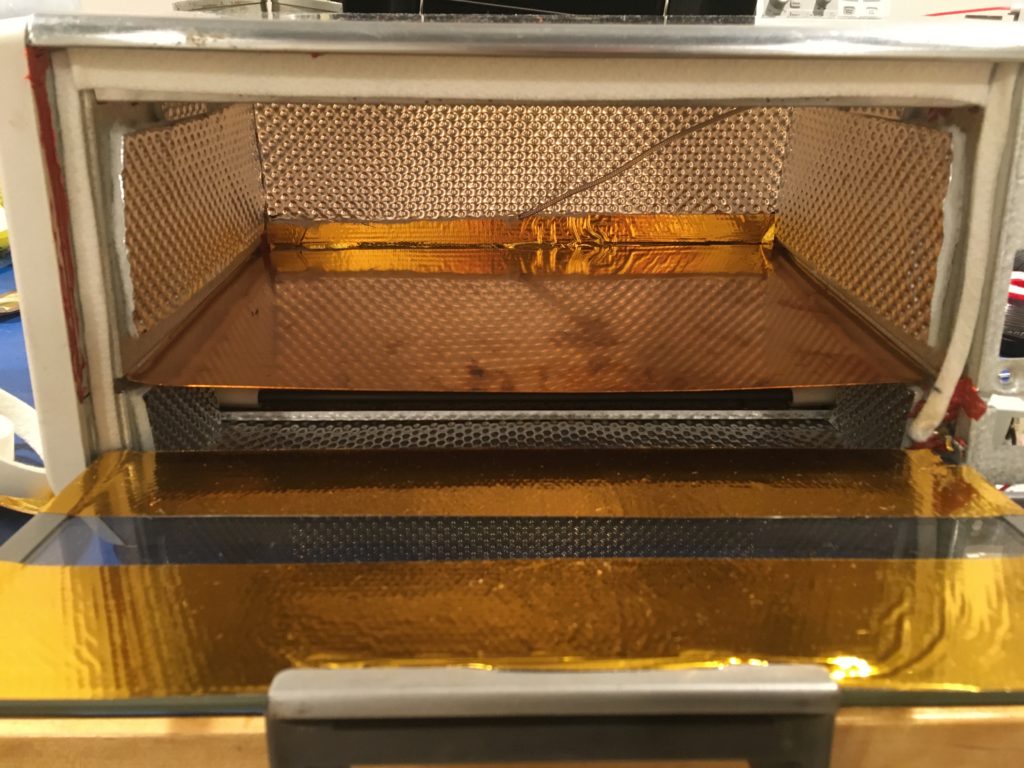
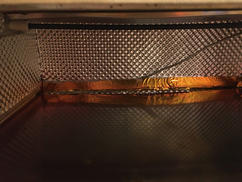
The next step is to add insulation to the inside. We used two different types. As much as possible we used the silver insulation as shown in the picture below. It’s floor and tunnel insulation used in automobiles around the exhaust so it is made for very high temperatures. You can find it here on Amazon. We liked the silver insulation as it’s a good thermal insulator, not just reflecting IR radiation back into the oven. It is tough to cut though. We used a good pair of scissors and still struggled. We would suggest spending some time trying to find a good method to cut it – our method took a lot of time and caused much frustration.
For areas such as the front window, or corners too difficult to get the thicker insulation into, we used Reflect-A-Gold. You can find it here. It’s really easy to work with, but does not have any insulation integrated into it. It works simply by reflecting IR back into the oven. The last step was the seal around the door. We used this stuff from Amazon. This is good to have as it keeps the flux and other fumes in the oven.
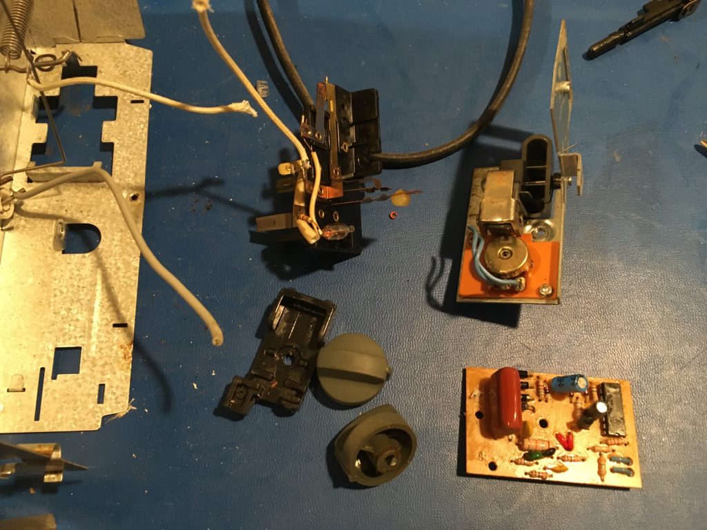
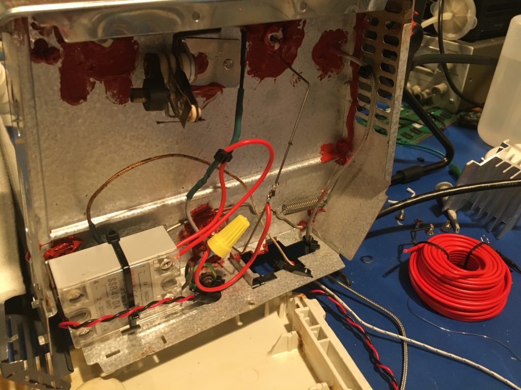
With the sealing and insulating complete, we began to prepare to place the new control electronics into the side. The picture below shows what we started with. We removed as much as possible any remnants of the old controls.
We then placed in the solid state relay into the enclosure and wired it up. We used 18AWG stranded wire to connect the relay to the oven elements. For the control wiring, note the twisted black/red pair wiring. We twisted them in hopes of reducing any EMI (electromagnetic interference). For the control wiring, there is only fractions of an amp of current, so much thinner/lighter wire can be used.
Electronics Setup
The electronics for the oven is fairly simple. Essentially, there are three components: the load, a switch, and a controller.
The load is the simplest part of the reflow oven build. The one decision is whether to wire the top elements separate from the bottom ones. Some controllers support both, but the rocket scream controller only supports driving both at the same time. It really is not a huge issue, as this is not anywhere near a production reflow oven, which use a conveyor belt and multiple zones to take a PCB through reflow.
The switch is a bit more complicated. The controller cannot drive the load directly as it requires more power than the controller can provide. Therefore, we use a switch to control the flow of mains (120V AC, or 230V AC). A normal mechanical relay is too slow and only has a lifetime of 100s of thousands of switches. With the controller switching multiple times per second, it requires a solid state switch. In the block diagram below, the controller applies a current to pins 3 and 4. This then biases LEDs, who’s photons trigger a triac. This then allows current to flow from pins 1 to 2. This current dissipates power as heat in the load (the heating elements in the oven).
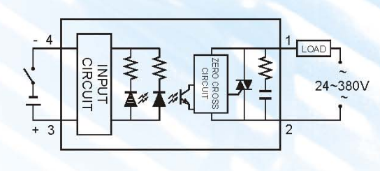
The last part is the controller. The controller drives pins 3 and 4 in the above diagram to turn the heating elements (the load) of the reflow oven on and off. The controller knows how long to let them run by some sort of temperature feedback, usually provided by a K-type thermalcouple. We will go into more detail on how to program and drive the controller in a later blog post.
Finishing Up
With everything wired up, we then insert the thermocouple into the oven chamber. We debated between just letting it rest above the PCB surface or to try and tie it to the PCB under reflow. In the end, we do not think it matters that much. To get it attached well enough to a PCB to have confidence of good thermal conductivity, we would need to attach the thermocouple via high-lead solder or else some epoxy. Either method takes too long for our needs, so we plan to simply tune the control loop such that the reflow profile is suitable to our needs. In the picture below, the thermocouple is in the back of the oven. We typically place the thermocouple in the air, 1 – 2 mm above the PCB being reflowed. We do notice a significant thermal gradient in the oven. We may try to characterize this, but that is for a later post.
And with that, we will wrap up this post! We will go into more detail in a future post about programming the Rocket Scream V2 as the user guide they provide is for the now obsolete V1. In addition, we will go into more detail about testing the oven and thermal profiles.
Leave a Reply